Copper Titanium Alloy
C1990-GSH(HP) - Copper Titanium Foil
Overview
- A Hyper copper titanium foil (model code C1990(HP)) offering the highest level of strength of any copper alloy.
- The high strength and excellent spring properties make it an alternative to beryllium copper foil.
- Higher thickness precision than conventional materials is achieved by optimizing the manufacturing processes.
This higher thickness precision in turn improves the stability of spring properties. - All production processes from metal melting to product-width slitting take place in our Kurami Works, enabling quick delivery time.
Features
- High strength
- Excellent spring properties
- Can be used in place of beryllium copper
- High thickness precision
- High reliability
- Excellent stress relaxation resistance
- Excellent fatigue properties
- Full-process production for quick delivery
Manufacturable thickness (typical dimensions)
- 30µm~100µm
- Maximum width 450 mm
Typical applications
- Connectors
- Spring material in autofocus camera modules for mobile phones
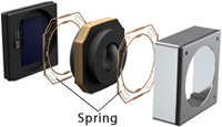
Table 1. C1990-GSH(HP) chemical composition (%)
| Cu | Ti | |
|---|---|---|
| Standard composition | Remainder | 3.0 |
Table 2. Physical properties of C1990-GSH(HP)
| Electrical conductivity | 8 | %IACS (@20℃) |
|---|---|---|
| Specific resistivity | 216 | nΩ·m (@20℃) |
| Thermal conductivity | 39 | W/mK |
| Linear expansion coefficient | 18.6 | ×10-6/K(20 to 300℃) |
| Modulus of elasticity | 127 | GPa |
| Specific gravity | 8.70 |
Table 3. Mechanical properties of C1990-GSH(HP)
(upper: typical values, lower: specification range)
| Temper | Tensile strength (MPa) |
Yield Strength (MPa) |
Vickers hardness (Hv) |
|---|---|---|---|
| C1990-GSH(HP) | 1400 1300-1600 |
1390 - |
400 - |
Figure 1. Histogram of thickness distribution in the longitudinal direction (comparison of high thickness precision material with conventional material; thickness 30µm)
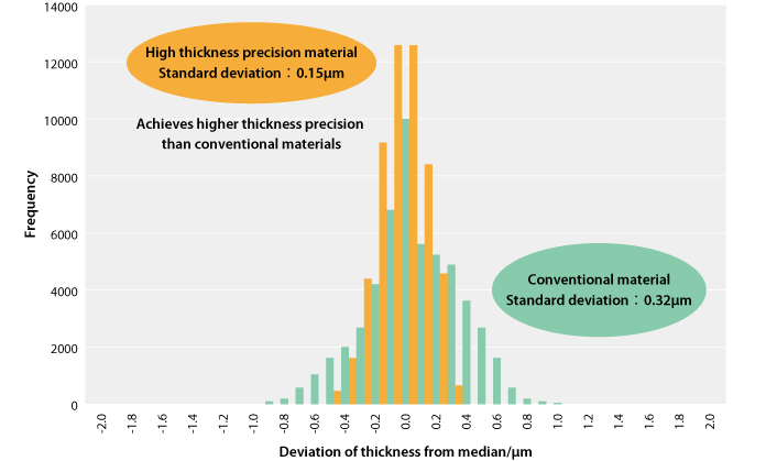
- Data obtained by X-ray measurements of thickness at the center of the transverse direction (perpendicular to the rolling direction) of the mother coil, taken every 0.01 seconds for approximately 1,000 meters.
- The values shown are typical values and are not intended as specifications.
Figure 2. Thickness distribution in the transverse direction (high thickness precision material N = 3, thickness 30 µm)
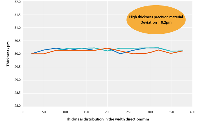
- Thickness distribution was measured in the transverse direction using a direct contact thickness gauge.
- The values shown are typical values and are not intended as specifications.
Contact Information
From the Web
Inquiries accepted 24 hours a day.